| 160m to 6m high perfomance receiver project . Back End Subsystem | |
| Home | Projects | Tech Info | Media | Links | Contact | Store |
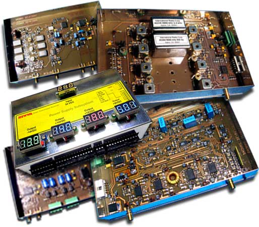
The Back End subsystem is the second part of the high performance 160m-6m HF receiver project. It comprises: IF Selectivity Board box unit IF Variable Gain Board box unit IF Detector Board box unit Audio amplifier box unit Power Supply Overall Control Logic |
 |
|||
Due the complexity involve in the construction of the units I started with easiest one, the Power Supply. The Rectifier Board |
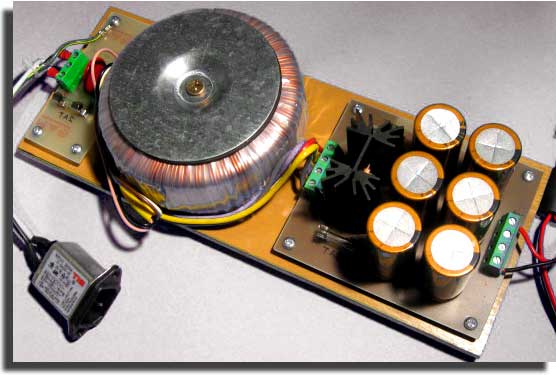 |
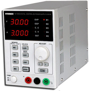
The rectifier board contains the mains toroidal transformer, rectifier and filtering providing the unregulated +24V raw DC voltage to the Switcher module. Due the high prices of the transformer and top quality aluminium electrolytic capacitors I decided to use instead a cheaper commercial laboratory grade power supply. Later I will decide whether to include it
Rectifier board documentation |
|
|
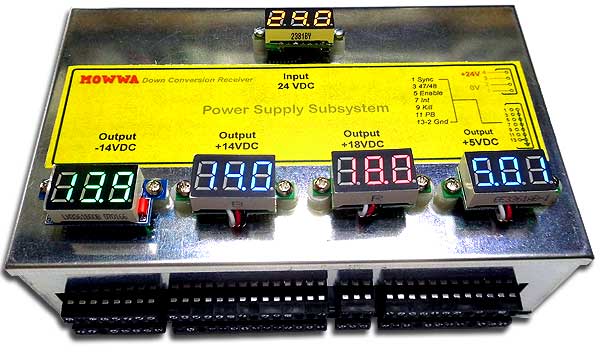
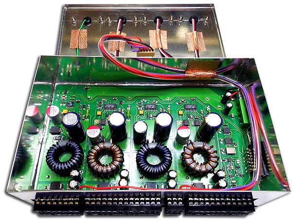
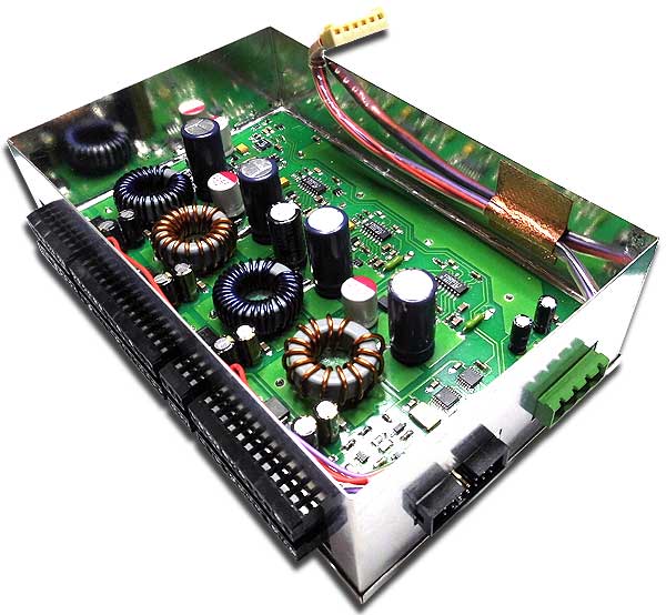
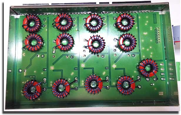
| The Switcher module box | ||
|
||
|
Switcher module documentation |
 |
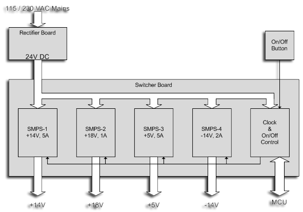
Power Supply switcher diagram |
|||
 |
|
|
|
Next: The Audio section (coming soon)
|
|
| Home | Projects | Tech Info | Media | Links | Contact | Store |