MF band Preselector project


Home Projects Tech Info Media Links Contact Store


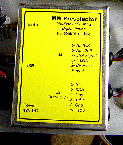
State of the Art, Passive Radio Preselector for MF band, digital tunable.

Covering the European MF band range from 526.5 kHz to 1606.5 kHz


Apart from normal Ham radio activities, my friend Jozef Balaz, DJ0DC and I, M0WWA, both share the same interest for DXing on Medium Wave band, aka AM Broadcast band.

The Problem.

On the one hand MW band receivers generally suffer from lack of selectivity and sensibility even the more expensive ones.
On the other hand, here in Europe, we have an AM Broadcasting band crowded of radio stations operating with one to tens of Kilowatts of RF output power together several monsters transmitting from hundreds of Kilowatts up to 2 Megawatts.
Our receivers are designed to accept only a certain maximum amount of radio frequency energy in the front end. If more energy is present there are simply many signals within the pass band for the receiver front-end “to swallow them” so several overload conditions results such as intermodulation and/or cross modulation.

The Choices.

The Antenna.

Antenna choice can make some difference in MW band. In our case both of us are using random length wire antennas, no significantly better choices available.

The attenuator. The “Kill 'em All” solution.

The idea behind the in -line antenna step attenuator is to reduce all incoming signals to the front-end enough to drop the overall energy in the circuit to below the maximum level that can be accommodated without either overload or intermodulation occurring at significant levels.
The issue is that the attenuator reduce and/or kill both desired and undesired signals due it affects all signals equally.
Although sometimes they are a helpful tool to take in account, antenna attenuator can’t be the unique solution.

The Filter.

Undoubtedly The Solution is to filter out the offending signals before they reach the receiver front-end without affecting significantly the desired signals. A Preselector connected in line with the antenna provides additional selectivity and protection to the receiver.
This reduces the receiver desensitisation and overload that would normally occurs in the presence of strong adjacent RF transmissions.
Any signal outside the pass band of a frequency selective filter is sharply attenuated. It does not drop to zero, but the attenuation can be as deep as the filter design allows it. Signals within the receiver’s pass band are barely affected by the filter; the filter insertion loss for in-band signals is, however, considerably less than for adjacent signals.
Because the range of frequencies to cover in narrow segments is 500 KHz to 1,600 KHz a selective tuning method is needed. The pre-filter system is complemented with two inputs antenna selector, variable step attenuator and low noise preamplifier.

Conclusion.

After the above reasoning we concluded we can not live without a proper MW band Preselector so we joined forces to build it.


The Design.

Due it is not a commercial project we enjoyed its design whitout budgetary constraint. 


Preliminary tests.


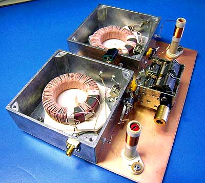
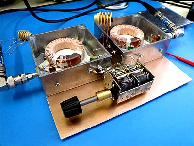
Testing a BPF build with toroidal iron core coils.


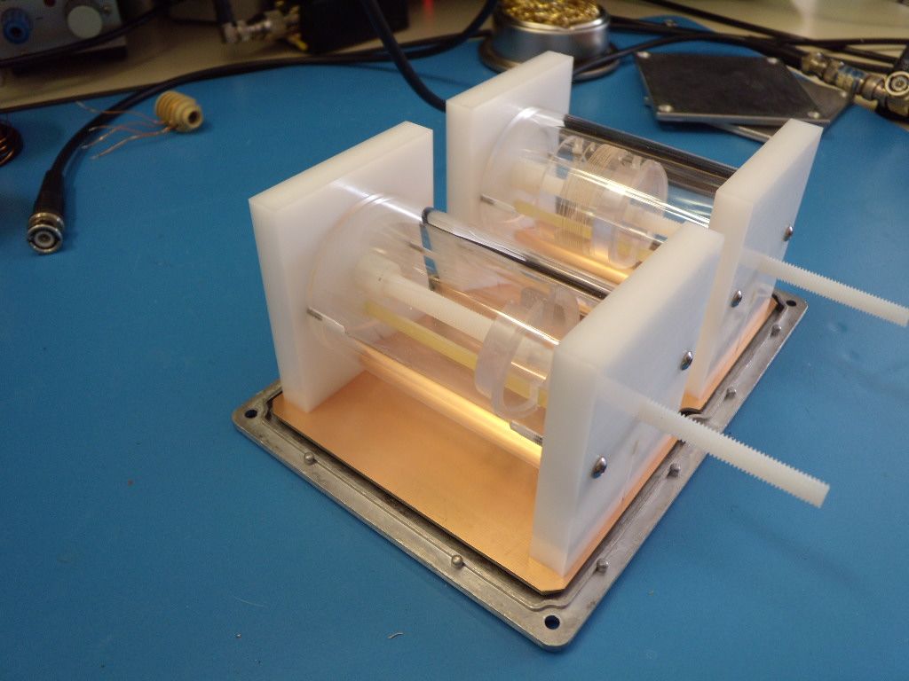
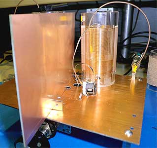
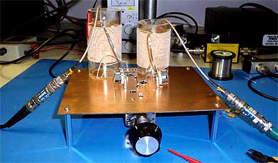
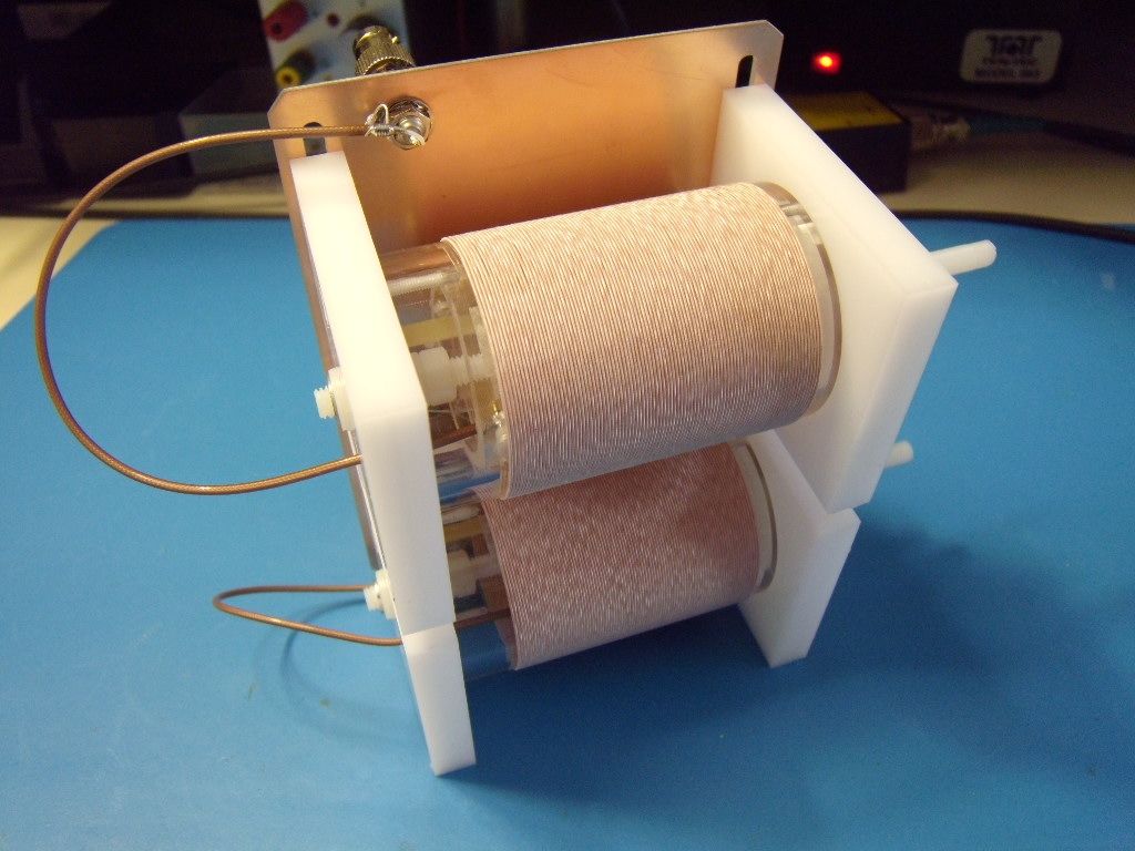
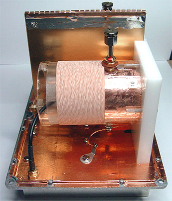
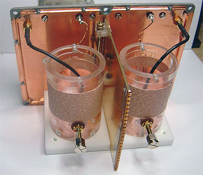
LC tank circuit air coils. Testing mutual coupling linear adjusting.


Testing the digital variable tuning capacitor.
Testing coils with HP 4342A Q meter.


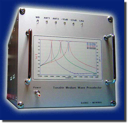
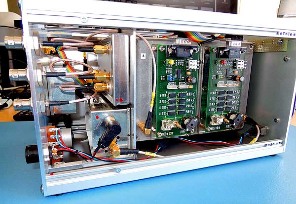
Finally after near two years of hard work the MW band Preselector project was completed.


The Circuitry.

Diagram

MW band Preselector architecture.

(click on picture icon to enlarge)


Plot

MW band Preselector response plot..

(click on picture icon to enlarge)


Referring to the above architecture diagram, the MW band Preselector circuitry comprises several modules build around a high selective band pass filter all assembled in a special made to order aluminium enclosure of 280x165x155mm (11.023x6.496x6.102 inch) in size. The Preselector total weight is 3.5Kg.
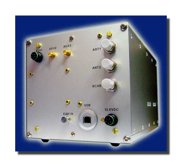
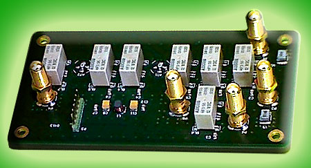
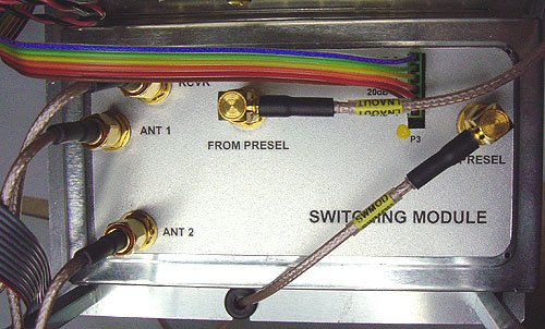
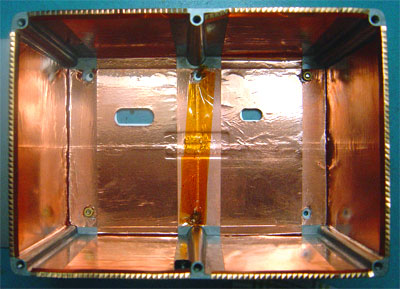
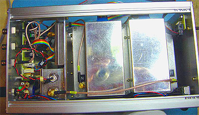


The switching module.

The switching module takes care of the inputting/outputting signals as well as their internal addressing.

The switching module features selection for two antenna inputs, 0dB, 10dB, 20 dB and 30 dB step attenuator, build around MiniCircuits PAT series attenuator cells, preselector by-pass function and signal addressing from/to the BPF module.

All switching functions are handled by the on board preselector microcontroller module via I2C bus, digital communication protocol system. A multipolar connector carrying control signals and power supply is included

A total of seven, professional grade, Axicom HF3-56 RF relays are used as switching devices providing negligible signal losses.

SMA type, RF connectors and RG-316 low loss coaxial cable for interconnection with other modules are used.

The switching module is assembled on a Duroid 5880 PTFE material grade laminate, gold plated for high RF conductivity PCB, carefully designed to minimise crosstalk among signal paths.

The whole switching set is mounted in a TEKO high frequency grade, hot tin-plated steel with finger-flanged lid enclosure in order to assure a good shielding.
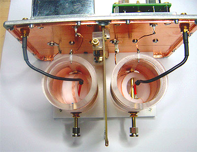
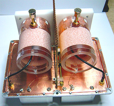
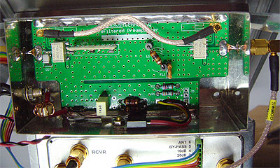


The Band Pass Filter module.

The BPF is the core of the preselector. Finding the best circuit configuration took lots of testing time and patience.


Several series and parallel resonant circuit topologies where tested in order to achieve maximum selectivity with minimum insertion loss cost but keeping an eye on the final size and weight of the Preselector. Eventually the best results were achieved using two weak coupled parallel resonant LC tank circuits.


To achieve a Q figure of 400 the resonant coils are wounded on large forms of 50mm in diameter using high quality Litz wire.


A critical aspect of the LC tank resonant circuit response is the input and load coupling circuits. Taps on resonant coils and primary-secondary mutual coupling linear adjusting were tested but end results were not acceptable so a more complex coupling mechanism was necessarily adopted, the old Variometer.


A Variometer is a pair of coils arranged in such a way that the axis of one can be rotated relative to the axis of the other. Rotating one of the coils alters the mutual inductance (coupling).


When the magnetic fields produced by the coils are in full or partial opposition, inductance cancellation occurs (mutual inductance is negative). When the fields add, the inductance increases (mutual inductance is positive). The mutual inductance is zero when the axes of the two coils are at right angles.


Filter coils coupling factor is regulated by a special wall, located between coils, acting as a weak coupling capacity. A variable mechanism lets a fine adjust of the coupling factor.

The BPF coils are assembled in a 171mmx120mmx105mm (6.732x4.763x4.133 inch) Hammond 1550F dietcast aluminium enclosure internally lined with copper foil to improve RF conductivity.


SMA type, RF connectors and RG-316 low loss coaxial cable are used to interconnect the BPF input/output signals with the switching module.


diagram

Variocoupler BPF diagram .

(click on picture icon to enlarge)


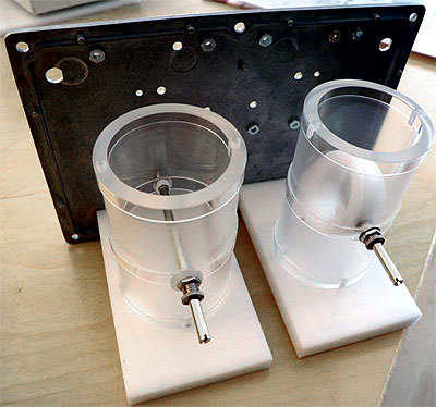
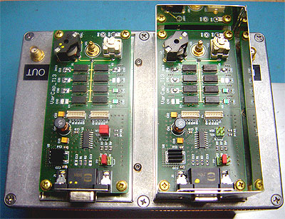
Digital Variable Capacitors. (DVC)
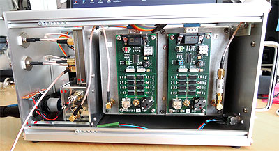

Two DVC sub modules are included in the BPF assembly.


Each DVC consists in a set of eight switchable Cornell Dubilier MC multilayer mica RF capacitors of 1 pF, 2 pF, 4 pF, 8 pF, 16 pF, 32 pF, 64 pF and 128 pF that emulates the variable capacitor needed to tune the resonant circuits.


Eight, professional grade, very low stray capacitance Meder CRF series RF relays are used as switching capacitor devices.


The on board preselector microcontroller performs the tuning task by adding or subtracting capacitor values in binary fashion in direct relationship with the tuning knob operated by the user. Increments or decrements are done in 2, 4, 10 or 20 steps.


DVC sub modules are assembled on a carefully designed Duroid 5880 PTFE material grade laminate, gold plated for high RF conductivity PCB.


Each DVC set is mounted in a high frequency grade tin-plated enclosure in order to assure maximum shielding among DVC sub modules and coils assemble.


The DVC units incorporate a multipolar connector carrying I2C bus control signals from the microcontroller and power supply.


The Low Noise Amplifier module. (LNA)

The LNA is based on a high dynamic range GALI-74 MMIC device from MiniCircuits that offers a gain of 25dB and a noise figure of 2,7dB.


The LNA gain can be regulated by means of the preselector on board step attenuator.


The LNA inorporates an 1.6MHz low pass filter in order to limit its large bandwith.

The LNA is controlled from the preselector on board microcontroller.

When switched Off the LNA is by-passed..
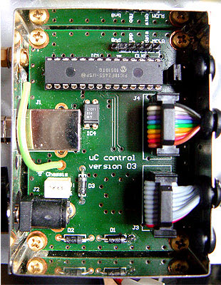


The Microcontroller module. (uC)

The on board uC handles all preselector functions. A 18F2455 PIC microcontroller from Microchip is used. It incorporates a full speed (v2.0) USB peripheral to communicate with the PC. via Virtual Com Port providing to the user with remote control from dedicated Graphic User Interface (GUI).

Features such as preselector tracking from the main receiver, via CAT commands communication protocol, Network connectivity, frequency calibration and several more auxiliary functions are provided by the uC.

The uC communicates with other preselector modules via I2C bus digital communication protocol system and/or logic digital ports.

Also the uC features, In circuit serial programming (ICSP). A suitable connector on board lets to program the uC firmware without remove it from the module.

A carefully PCB design includes strong power supply decoupling circuitry.

The uC module is located in an well shielded enclosure avoiding introducing noise generated by the microprocessor itself and the noisy USB bus.


The Software.


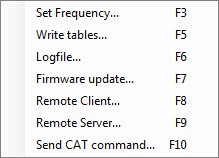
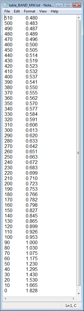
A PIC microcontroller firmware and a PC software application running under Windows OS were developed specially for the MW band Preselector.

The user remotely commands the MW band Preselector by means of the Graphic User Interface (GUI) console on a PC.

In addition to the GUI controls a context menu provides additional features and utilities.

The application console runs under Windows (32 & 64 bits) operate systems.

By default, the MW band preselector application starts in by-pass state on power-on. In this state, all controls are disabled except the antenna selection and the context menu.

The software application includes a calibration table file needed by the microcontroller on board to translate frequency commands into tune capacity values. If it is needed the user can edit the file and recalibrate the preselector with the aid of a signal generator.

Context menu.

Table

Calibration table file.


The Graphic User Interface (GUI)
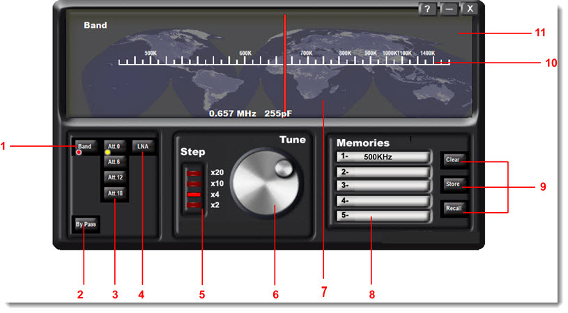


1- Band selection.
Click over band push-button to live By-pass state.

2- By-Pass.
By-passes the preselector. Default on power-on. In this state
all controls are disabled except antenna selection and contextual menu.

3- Input attenuator.
0dB, 10dB, 20dB, 30dB to choose.

4- Low Noise Amplifier. LNA ON/OFF.

5- Tuning step. x2, x4, x10, x20.
Position x2 performs tune scan by clicking on the dial.

6- Tuning knob.
Performs tuning rolling the mouse wheel. Also by pressing left or right arrows on the keyboard. Adjust to maximum signal or background noise.


7- Dial. Displays the actual tuned frequency and the corresponding capacitor value. Also a context menu is available.

8- Mnemonic text box. A brief caption can be written in the text boxes. Five memories can be stored.

9- Memory management.

10- Frequency scale. Frequency references on the scale are updated in accordance with the frequency calibration tables.

11- Context menu.
Right mouse button click on dial or function key F2 opens the context menu.


Home Projects Tech Info Media Links Contact Store
Copyright MMVI by Juan Jose de Oņate M0WWA, Webmaster
For any comments regarding this web site, please e-mail me.