My implementation of N2PK Vector Network Analyzer |
| Home | Projects | Tech Info | Media | Links | Contact | Store |
My implementation of N2PK Vector Network Analyzer project60kHz to 60MHz laboratory quality Vector Network Analyzer. |
| Overview
I selected the N2PK VNA project for laboratory and antenna measurements because of its exceptional design, precision, and reliability. Comprehensive documentation on the N2PK VNA can be found at this site: https://groups.io/g/N2PK-VNA Since its release several years ago, hundreds of N2PK VNAs have been built worldwide for both amateur and professional use, demonstrating its outstanding performance. The N2PK VNA is not just a VNA; it is a "Lab in a Box" that performs various functions due to its dual DDS generators and dual detectors. It can function as an RF generator, sweep generator, power detector, vector voltmeter, IP3 measurement tool, antenna analyzer, and more. Rudy Severns N6LF conducted comparative measurements of several VNAs using different loads, with the HP3577A VNA serving as a reference.
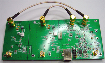
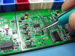
N2PK Vector network analyzer comparison. The Hardware. VNA core board.I have constructed several N2PK VNAs, utilizing the dual detector PCB, version 4xx (parallel port) and version 5xx, ( USB ) designed by Ivan Makarov VE3IVM under the author's supervision. Detailed information about the board is available at N2PK-VNA Group https://groups.io/g/N2PK-VNA To maintain the published performance standards, all components used in the assembly adhere to the author's specifications. Each assembled board undergoes a 24-hour burn-in test.
|
Specifications: - Frequency range: 60kHz to 60MHz - Dynamic range: 120dB - Number of detectors: 2 - Detector ports input impedance: 50 Ohm - Detector ports Return Loss: 30 dB - Detector ports input power: +10dBm - Detector ports ADC resolution: 24 bit - RF DDS port max output power +4 dBm over 50 Ohm - Detector Resolution Bandwidth: Selectable from 7Hz to 3.4kHz - Master Oscillator: Connor- Winfield 156.250MHz or equivalent. - Features: VNA, Dual RF signal, Sweep generator, Vector Voltmeter, Power Detector. - PC interface: High speed USB v2.0 - Power Supply:Dedicated external 12V /500mA min. - Aluminium enclosure: Hammond model 1455T1601 - Size: 163mmx160mmx51.5mm.(6.417x6.29x2.028in) |
|
|
|
The Software application "My VNA" by Dave Roberts G8KBB
|
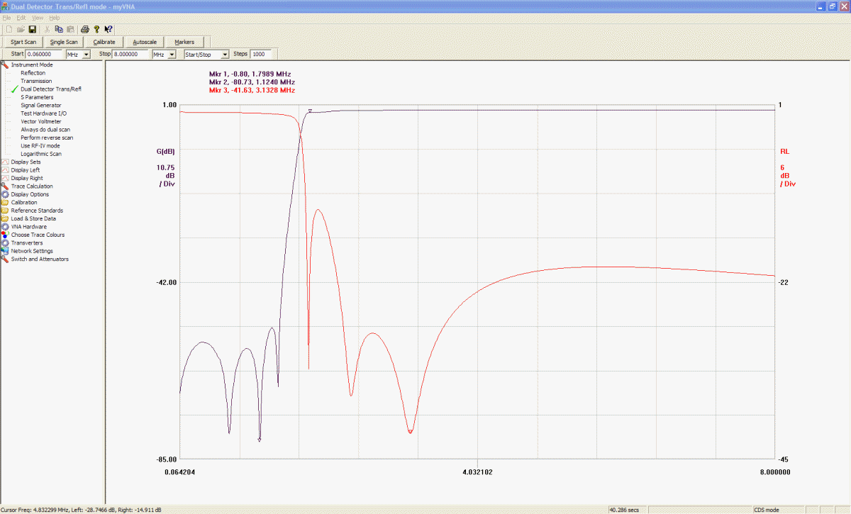
"My VNA" Graphic User Interface snapshot |
"My VNA" Software application features myVNA offers the following: |
|||||||

|
|
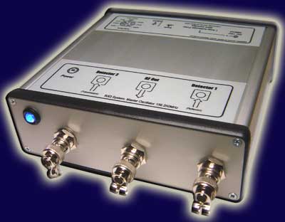
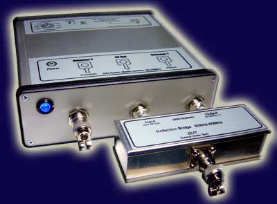
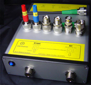
Boxed standard BNC version
 |
 |
||
Front view. BNC connectors with protective anti-dust caps Standard BNC type. |
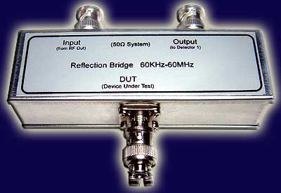
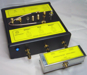
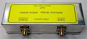
Measurement bridge plugged |
 |
 |
||
 |
 |
||
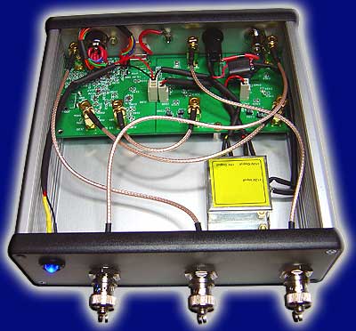
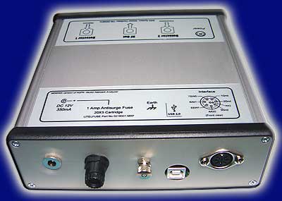
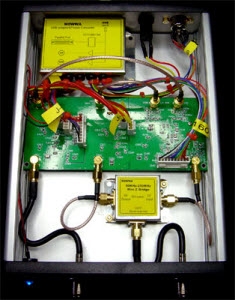
| VNA open | VNA rear view |
|
|
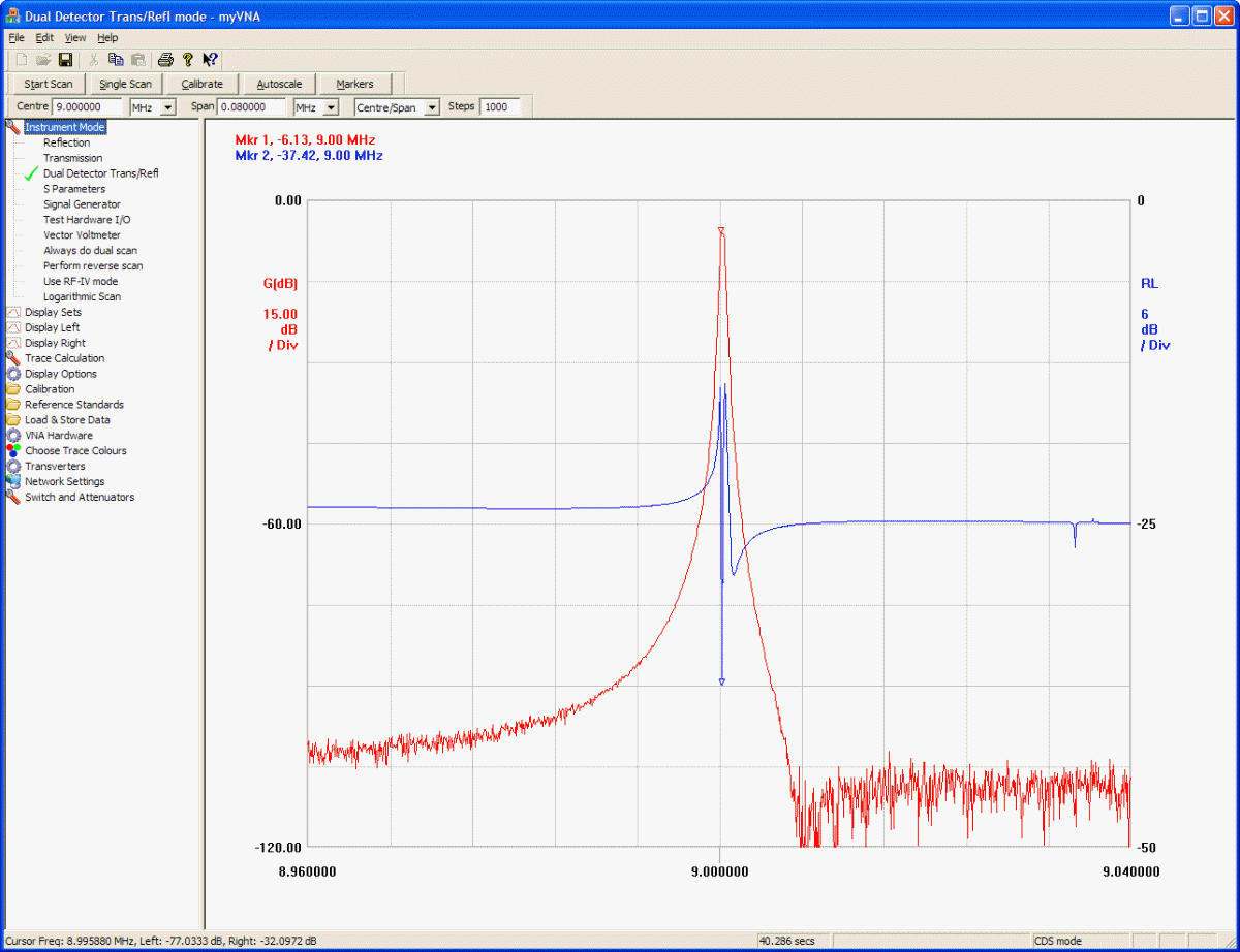
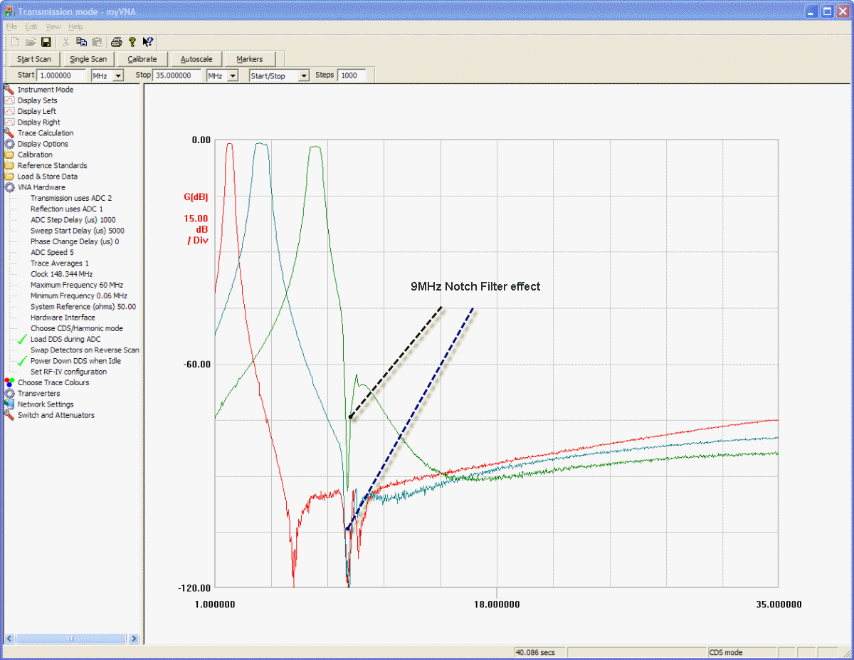
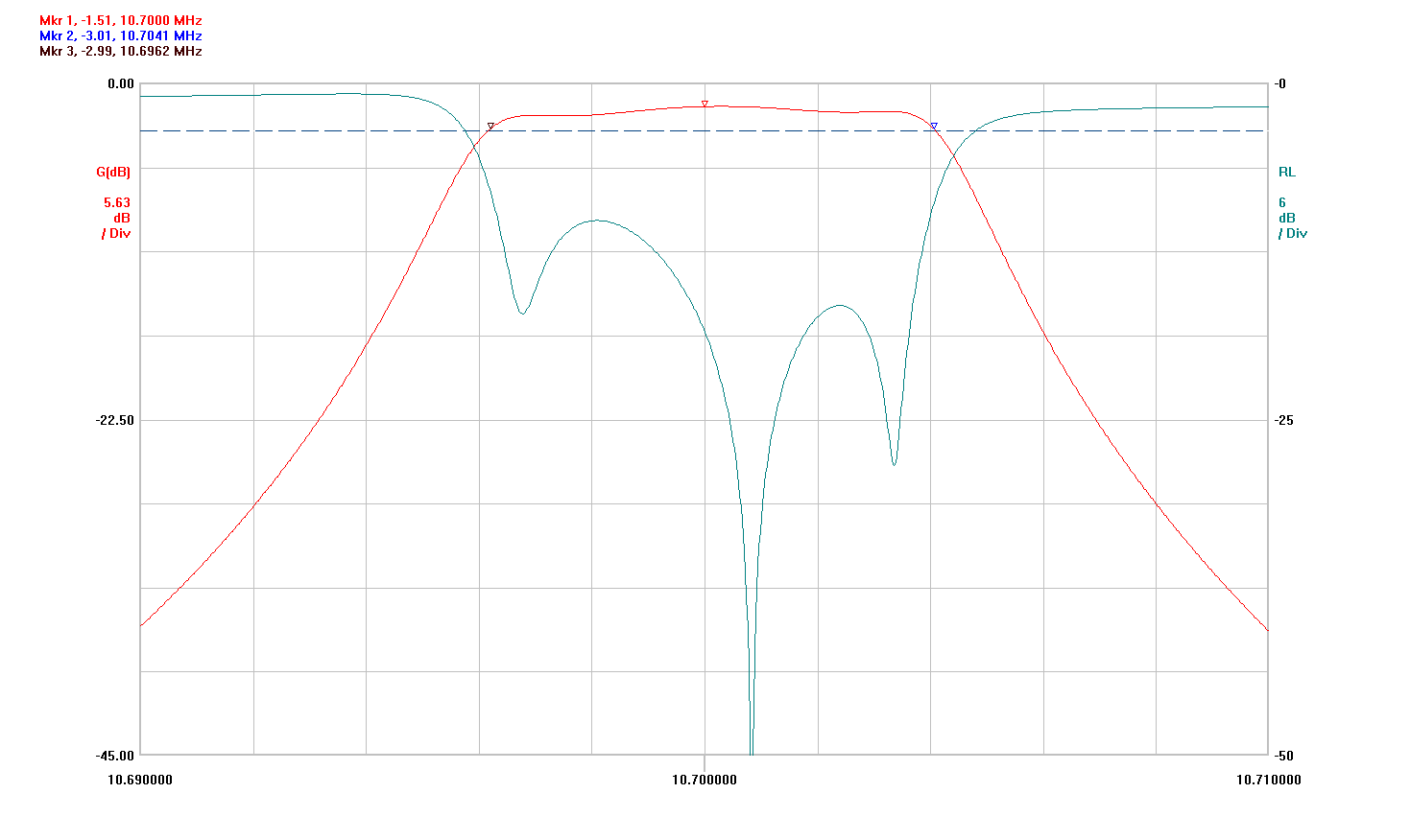
| Some snapshots using "My VNA" program software. (click on picture to enlarge) |
9MHz CW Xtal roofing filter |
160m, 80m, 40m BPF |
10.7 MHz crystal BPF response. |
||
|
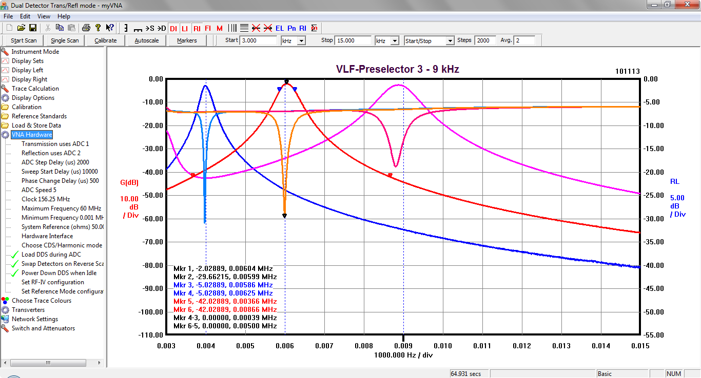
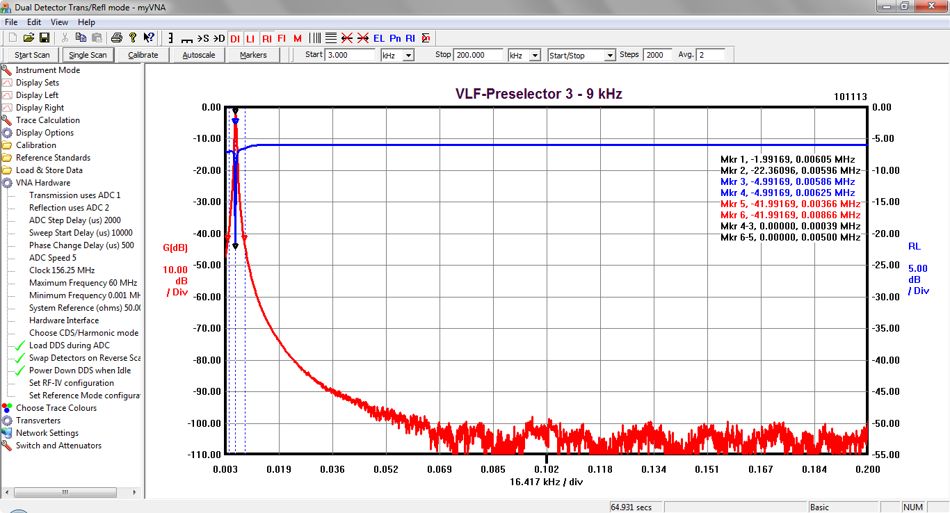
Working on Very Low Frequencies. |
Working on Very Low Frequencies.
|
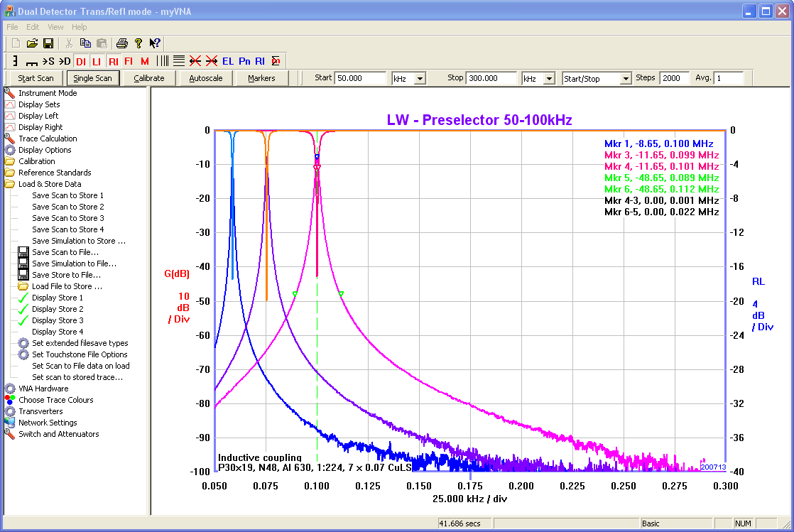
Working on Low Frequencies. |
||
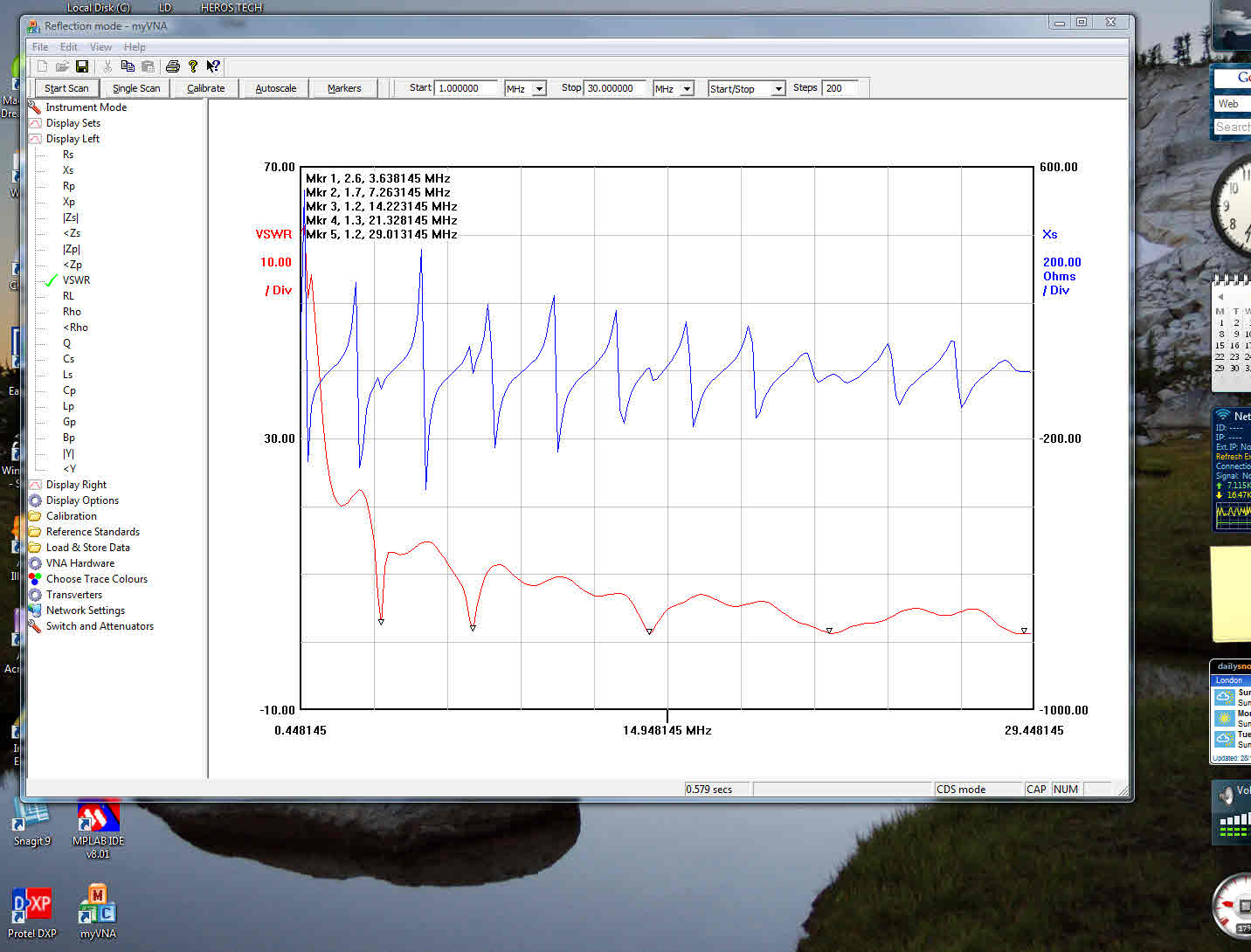
Diamond W-8010 80m/40m/20m/15m/10m |
VSWR-Xs |
BroadCast Band (BCB) Rejection Filter |
||

|
|
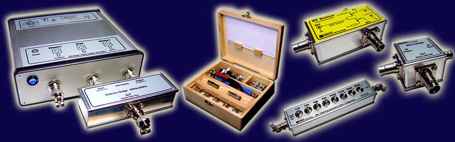
Some versions
|
||||
 |
 |
|||
N connectors
|
SMA connectors
|
|||
 |
 |
|||
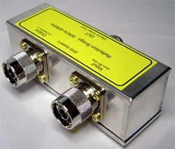
N connectors bidge |
SMA connectors bridge |
|||
 |
 |
|||
| Measurement bridge embeded for antenna measurements (board v4XX) |
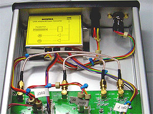
With USB adaptor/Power converter |
|||
|
|
| Home | Projects | Tech Info | Media | Links | Contact | Store |